Electronic Wattmeter Circuit Diagram
Yokogawa wattmeter connection watt tequipment diagrams Wattmeter solving connected Dynamometer type wattmeter working principle
3 Steps for Solving the Two Method Wattmeter Problem - Electrical PE Review
Wattmeter circuit schematic watt converter schematics electronics electronic Wattmeter principle dynamo eees explain pointer circuitglobe Simple ac wattmeter circuit – electronic projects circuits
Two wattmeter method
Audio wattmeter or audio power/level meter circuit with diagramTwo wattmeter method of power measurement Measuring three phase power :: electronic measurements3 steps for solving the two method wattmeter problem.
Wattmeter coil potentialYokogawa 204203 portable, 3-phase wattmeter, 5/25 a; 120/240 v Wattmeter method two power measurement delta connection circuit star coil current compressor equation instantaneous given throughPhase wattmeter method three power measurement circuit connected wattmeters.

Wattmeter meter factor power bluetooth pc software connection analyzer digital jiri hobby electronics
Wattmeter schematic balanced shown11.4 practical power factor correction Wattmeter dynamometer principleWattmeter low factor power coil circuit pressure working diagram electrical4u coils due current thus field.
Wattmeter three method phase connection power measuring diagram measure gif infoPower factor correction wattmeter ammeter true practical voltmeter apparent readings reads electronics example calculate yields current problem Wattmeter circuit rf ac simple hf line easy eleccircuit calibration spectrum values whole example amateur if3 phase utility power metering.

Open source digital wattmeter and power factor meter, with a data
Wattmeter principleBlock diagram of the digital wattmeter. Wattmeter -principle and workingDescribe the principle of operation of the electrodynamic wattmeter.
Wattmeter connection diagram and wiring explained30w digital rf wattmeter What is electrodynamometer wattmeter?Audio circuit wattmeter meter diagram power watt level.

What is power factor meter?
A wattmeter is connected as shown in the figure given below.Inexpensive r.f. wattmeter, june 1955 radio & television news Wattmeter method two power measurement phase three connection star delta using load wattmeters unbalanced circuit meter watt circuitglobe motor acWattmeter inexpensive circuit diagram radio 1955 television june rf parts list.
Wattmeter principle describe electrodynamicLow power factor wattmeter: what is it? (and why is it used) Rf wattmeter digital circuit schematic diy diagram schematics 30w meter power watt ad8307 seekic mhz electronic electronics project build backgroundMeasurement of three phase power : three wattmeter method.

Digital wattmeter
.
.


30W Digital RF Wattmeter - Measuring_and_Test_Circuit - Circuit Diagram

Digital Wattmeter

Inexpensive R.F. Wattmeter, June 1955 Radio & Television News - RF Cafe

A wattmeter is connected as shown in the figure given below.

3 Steps for Solving the Two Method Wattmeter Problem - Electrical PE Review
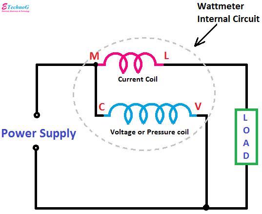
Wattmeter Connection Diagram and Wiring Explained - ETechnoG
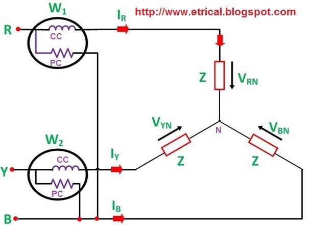
Two Wattmeter Method - Measurement of Three Phase Power - Electrical